How to Read Vsync From Dvi-d Spatial Light Modulator
 Spatial light modulator (SLM) is a general term describing devices that are used to modulate amplitude, stage, or polarization of lite waves in space and time. HOLOEYE´s Spatial Calorie-free Modulator systems are based on translucent (LCD) or cogitating (LCOS) liquid crystal microdisplays.
The use of LC materials in SLMs is based on their optical and electric anisotropy. A certain gray level represents a defined average voltage across the LC prison cell. This voltage leads to a variable tilt of the LC molecules due to their electric anisotropy. As LC molecules likewise prove optical anisotropy this tilt changes the refractive index of the LC molecules (for suitable incident polarization, dependent on device version) which causes a modified optical path length within the LC cell. The addressed gray level is now converted into a phase level.
HOLOEYEs SLMs are based on vertical aligned nematic (VAN),parallel aligned nematic (PAN) or twisted nematic (TN) microdisplay cells. In a twisted cell, the orientation of the molecules differs past typically 45°/90° betwixt the summit and the bottom of the LC prison cell and is bundled in a helix-like structure in betwixt. In VAN / PAN cells the alignment layers are parallel to each other, and so the LC molecules accept the same orientation.
 To use an SLM in aamplitude modulation style you demand linear incident polarisation. The transmitted or reflected light has to be guided through a 2d polariser (analyser) that is crossed to the incident polarisation. For phase modulation a setup without an analyser is used. With devices based on twisted nematic LC or LCOS displays the twist ever causes a polarisation issue (aamplitude modulation) and no phase only modulation is possible (phase more often than not modulation).
With VAN / PAN displays it is possible to modulate the stage without influence on the polarisation / amplitude (phase only modulation) past using incident polarization forth the LC director axis.
HOLOEYE Spatial Light Modulators:
- Resolution: 1920 × 1080
- Pixel Pitch: iv.five µm
- Fill Factor: 91 %
- Wavelengths Range: 420 – 650 nm,
1400-1700 nm
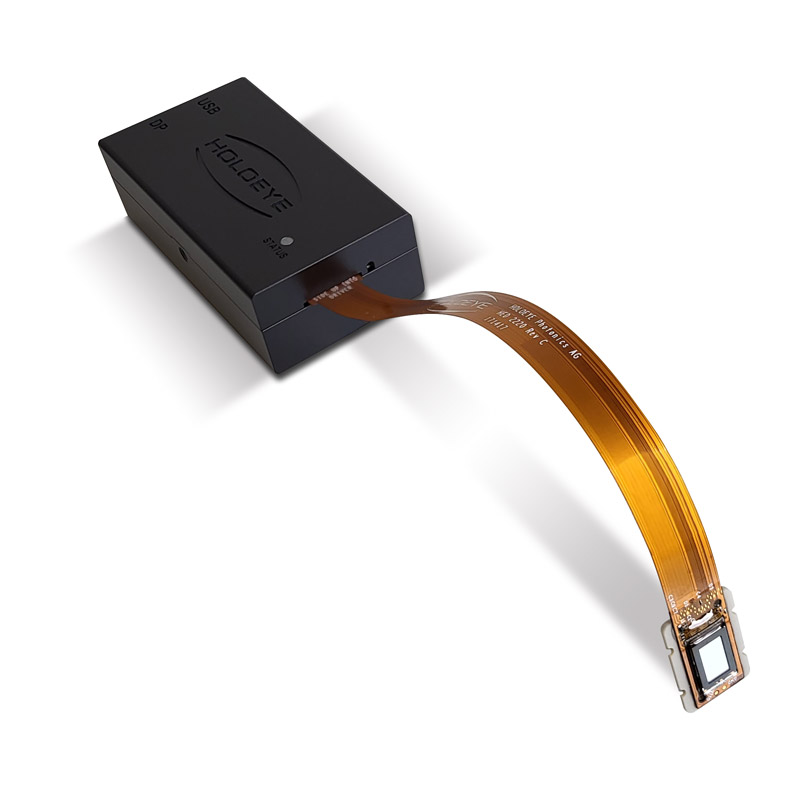
The LUNA Spatial Calorie-free Modulator is our most compact SLM platform for integration into small sized or even portable solutions.

- Resolution: max. 4160×2464 (4000×2160)
- Pixel Pitch: three.74 µm
- Fill Factor: 90 %
- Wavelengths Range: 420 – 1100 nm (Different Versions),
1400-1700 nm
The GAEA is currently the highest resolution SLM on the market with extremely small pixel pitch.

- Resolution: 1920 x 1080
- Pixel Pitch: 8.0 µm
- Fill Factor: 93 %
- Wavelengths Range: 350 – 1700 nm (Unlike Versions)
The PLUTO-two.ane SLM is our all-rounder within our product range. It is the best qualified and diversified SLM platform with many versions optimized for specific requirements. Besides PLUTO is already implemented in many industrial applications.

- Resolution: 1920 x 1080
- Pixel Pitch: 6.4 µm
- Fill Factor: 93 %
- Wavelengths Range: 420 – 1100 nm (Unlike Versions)
The LETO-3 is our fast SLM platform with high ring width. The SLM is capable of color sequential phase functioning.
![]()
- Resolution: 1024 ten 768
- Pixel Pitch: 36 µm
- Fill Factor: 58 %
- Wavelengths Range: 420 – 800 nm
The LC 2012 is our depression budged basic SLM. With the compact and robust design it is a good solution for teaching and instruction. There is also an education kit available.
- Download PDF: Brochure Spatial Light Modulators
- Download PDF: Application Notation SLMs for CFS
Definitions of Specs
- Resolution: Number of pixels (width x height)
- Pixel Pitch: Size of a pixel including the interpixel gap
- Fill Factor: Surface surface area of the brandish which tin actively used. In that location are gaps between the pixels at which the incident low-cal is scattered.
- Active Area: Size of the actual adressable/usable display expanse.
- Addressing: Number of gray levels / stage levels that can exist addressed. This can vary with addressing sequences.
- Signal Formats: Input signal format. Typically HDMI or DVI.
- Input Frame Rate: Addressing speed of the input bespeak (typically DVI / HDMI video frame rates of 60 Hz for monochrome applications).
- Response Fourth dimension: The response time is defined as the switching fourth dimension from 10% to 90% and from 90% to 10 % (rise and fall fourth dimension). The actual response time of the liquid crystal is adamant by the properties of the used liquid crystal material, the thickness of the LC layer, the used drive sequence / calibration (the actual voltages applied to a pixel) and temperature.
For stage SLMs the response fourth dimension typically is below the Input frame rate. - Reflectivity: Amount of calorie-free which is directly reflected (0-order of a not-addressed display). The reflectivity is non 100% as some of the calorie-free is diffracted into higher orders due to the grating like structure of the pixel matrix. Some role of the light is also scattered and absorbed at the interpixel gaps. In addition the reflectivity of the aluminum mirror is limited (dependent on wavelength).
Addressing the SLM:
 The optical part or data to be displayed on HOLOEYE Spatial Low-cal Modulators can be taken direct from an optic design software or an image source and can exist transferred by a computer interface. Using DVI/HDMI ports of standard PC graphics cards, the Spatial Calorie-free Modulator can be used just similar an external plug & play monitor (eastward.g. in extended desktop mode for a 2nd monitor) and no special software or drivers are necessary to operate the SLM. No thing which software is used to summate optical functions, if you lot are able to address a bitmap paradigm on a 2nd monitor output of the graphics carte you lot are able to operate the SLM. Also standard prototype viewer software tin be used.
For an like shooting fish in a barrel first and even more convienent functioning HOLOEYE provides a software package with each SLM. It contains a Blueprint Generator Software (for calculation of different optical functions), a Slideshow Player software (for easy addressing of precalculated functions or images on the SLM) and an SLM Brandish SDK for different development environments. As well a Configuration Manager software is included for convenient configuration of the Spatial Light Modulator.
Possible Spatial Light Modulator Applications:

- Imaging & Project
- Display Applications
- Holography (Display holography, holographic memory, holographic recording and security systems, including digital holography)
- Holographic Projection
- WSS – Wavelengths Selective Switching
- Axle Splitting
- Laser Axle Shaping
- Coherent Wavefront Modulation
- Phase Shifting
- Optical Tweezers
- Laser Pulse Modulation
At our "Papers & Reference" department we provide links to publications and papers for many different SLM fields of awarding.
How to Read Vsync From Dvi-d Spatial Light Modulator
Source: https://holoeye.com/spatial-light-modulators/
0 Response to "How to Read Vsync From Dvi-d Spatial Light Modulator"
Post a Comment